

Best Practices for Oil Lubricating Your Industrial Equipment
Posted on 04/16/20 in: Technical Knowledge | | General Industry | Author: Michael Holloway - MLE, CLS, LLA (I, II), MLT (I, II), MLA (I, II, III), OMA 1, CRL
The application of an oil can be broken down into a total loss application, a self-contained application, or a circulating application. The total loss, or once-through oiling is so named because the oil passes through the bearing only once and is lost for further use. It is also called “All Loss” oiling because the oil is used only once. Methods of this type include hand oiling, drop feed oiling, wick-feed oiling, and bottle oiling.
Hand oiling is the direct application of oil to a moving machine part from a hand oil can. An excess of oil is applied, which soon runs off, leaving the bearing to operate with insufficient oil until the next oiling. For this reason, bearings lubricated by hand oiling are not as well protected against wear as those on which more reliable oiling methods are used.
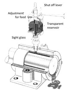
Drop feed oilers usually consist of a glass or plastic reservoir, a needle valve feed rate adjustment, a snap level shut-off, and a sight glass for observing the feed rate. They are generally used on lightly loaded, horizontal bearings that require a low rate of oil supply.
An electrically controlled form of drop feed oiler can be fitted with a large capacity reservoir and a manifold providing individually adjustable drop feeds for several bearings. Lines of tubing convey the lubricant to various bearings. A solenoid is a valve that opens and closes when the machine motor is started or stopped, and it controls the flow of oil from the reservoir to the feed control manifold.
Wick Oilers have a wick of loose textured, long fiber wool that supplies oil to the bearing through capillary action. Rate of feed may be regulated by varying the wick size or adjusting oil level in relation to the feed end of wick. Raising the wick will stop oil flow. The underfeed oiler consists of a metal reservoir with a shank that threads into a hole in the bearing housing. Oil feeds up the wick to the shaft through the hole in the underside of the bearing sleeve. Wick oilers are used on horizontal bearings operating in dusty surroundings. The wick serves as a filter to prevent contaminants from reaching the bearing. When the wick becomes choked with dust it must be cleaned or replaced. When the wick end becomes glazed from the rotating shaft, it should be trimmed off to provide a fresh surface. These are often used in traction motor bearings in railroad applications.
The bottle oiler consists of an inverted glass bottle mounted above the bearing and fitted with a sliding pin, which rests on the journal. When the journal rotates, it vibrates the pin. The vibration encourages a flow of oil from the bottle to the bearing through the space between the pin and its sleeve. The following are considerations for the oil cup method:
- Usually used to transfer large quantities of oil (large trunnion bearings)
- Speed limited
- Require shaft rotation to work
- Some delay in quantity transfer
- Work whenever shaft turns
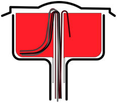
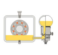
The constant level oiler consists of an inverted glass or plastic bottle with a neck extending into the oil in an overflow cup of the bearing reservoir. When oil level in the bearing reservoir falls below the end of the bottleneck, air is admitted into the bottle through a vent. Lubricant flows from the bottle to overflow cup and thence into bearing reservoir. When correct oil level is re-established, oil covers the bottleneck and prevents any more air from entering the bottle. A constant level is thereby maintained in the bearing reservoir. This offers the advantage of an auxiliary reservoir.
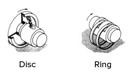
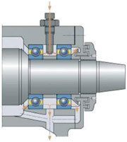
In, the ring oiling method, a metallic disc or ring, larger in diameter than the journal, rides on the journal and turns as the journal rotates. The ring, dipping into the oil, carries it to the top of the journal where it flows along and around the journal, providing lubrication before returning to the reservoir.
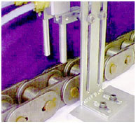
Chain oiling is similar to ring oiling except that a small-linked chain is substituted for the ring. The chain will carry a larger volume of oil than the ring. An oil ring or collar may be used to carry oil from the reservoir to journals turning at speeds so high that rings and chains would slip. The collar, fastened to the journal, dips into the oil reservoir as the journal rotates, carrying the oil to an overhead scraper which removes and distributes it along the journal.
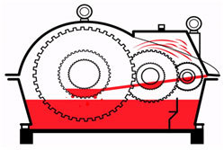
Splash lubrication is used by most internal combustion engines and many gears. The moving elements dip into a bath of oil and splash lubricant onto other components.
Mechanical lubricators consist of an oil reservoir; one or more pumps (usually plunger type), operated by rotary or ratchet mechanical drive or by electric motor; feed rate adjustment for oil delivery; usually a sight feed for checking delivery of lubricant; and an oil strainer at the intake of each pump.
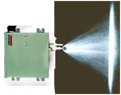
Oil mist lubrication uses a stream of compressed air to break up the oil into a fine mist. A fine dry fog of oil is conveyed from the generator through tubing lines to the bearings. From there, the oil particles are reclassified on impact and are converted to a wet fog at point of application. Turbulence will cause the droplets to recombine. Distribution lines are tied to the top of the main line to prevent any contaminants from being transferred to the equipment being lubricated. Very small quantities of oil are consumed.
The flow of air helps keep dirt out of the bearings and has a cooling effect. Oil mist is especially effective at cooling high-speed bearings. Oil mist has the following advantages over other lubrication systems:
- Constant supply of fresh lubricant
- Slight pressurization helps to reduce contamination
- No moving parts, or cyclic mechanism in the system
- Alarm systems monitor flow rate and oil level
- Low lubricant consumption reduces lubricant cost
- Reduces temperature in bearing housings by up to 30%. However, the advantages may be offset by disadvantages:
- High initial cost
- Difficult to set and maintain flow rates
- Some environmental and/or health concerns if stray mist is not contained
- Very sensitive to temperature changes
- Return lines must capture mist that is not reclassified to liquid
- Potential varnish and sludge if oil overheats excessively
Spray lubrication for oil is used to lubricate plain roll neck bearings on mills. A spray gun, similar to those used for paint, uses compressed air to spray gear teeth with a film of grease sufficient for lubrication.
Circulating systems provide a continuous supply of oil to bearings. Since oil is continuously re-used, oil can be strained, filtered, and cooled. Oil pressure is controlled by a relief valve or orifice sizing. In a direct circulating system, a pump is used to meter the lubricant. In an indirect system, the pump builds pressure, and metering valves in supply lines meter the amount of lubricant. Two reservoirs feed gravity systems: one above the highest bearing to be lubricated and the other below the lowest bearing. Oil leaves the upper reservoir, lubricates the bearings by gravity, drains to the lower reservoir, and is returned to upper reservoir by means of a pump. Pressure feed systems use a pump to force oil to bearings from where the oil drains to a reservoir by gravity. Cooling may be used on the return lines. Systems of this type are useful where large volumes of oil are handled.
Reservoirs should allow oil to dwell long enough to separate air, water and solid impurities. Fluid residence time can vary from 3 minutes to 60 minutes depending on the system. Low oil depth permits faster escape of entrained air and quicker settling of water and solids. A long tank places the pump suction farther from the oil inlet to give the longest possible oil path. These factors lead to the following typical reservoir proportions: In all methods of reservoir lubrication, it is important that the reservoir be checked periodically to be certain that proper oil level is maintained. A level gauge is provided in the lower part of the reservoir for this purpose.
Vents allow moisture and vapor to escape. Filters and desiccant breathers prevent dust and moisture from contaminating the oil. Large oil systems are frequently vented to a vapor extractor pump. In addition to the vent above the maximum oil level should be provided for tank inspection and cleaning. Headspace is needed in the design of oil reservoirs to allow for thermal expansion, turbulence, foaming and air release, and system fluctuations.
Tags: lubricant application, lubricant, gears, gearboxes moving parts, lubricant use, reservoirs, hand oiling, drop feed oiling, wick-feed oiling, bottle oiling, constant level oiler, ring oiling method, chain oiling, splash lubrication, mechanical lubricators, oil mist lubrication, circulating oil systems